Radiance is the world's leading lighting simulation toolkit. It is used by lighting engineers internationally when they want to predict how a space will be lit, either through natural or artificial lighting. It is also unique in its quest for "photometrically correct" rendering (see a comparison of Radiance and other rendering engines here).
The most common usecase for rendering with Radiance is for scientific quantitative analysis. In contrast, the CG community (such as Pixar) has the goal to make the unreal look real, to give wonder, surprise, and to make you believe in another artistic world.
Somewhere between the scientists and the artists lie those who design the world around us. They are the architects, industrial designers, and installation artists. The unreal, at the end of the day, needs to manifest in a physical creation that can be manufactured and placed in space. A mixture of physical prototypes virtual prototypes are used to flesh out the idea. But how do we guarantee that the physical creation will match the virtual prototype? How can we trust our virtual sketch?
In this article, I will give a breakdown of a living room render done in Radiance. This is a proof of concept of implementing a level of qualitative detail that isn't usually done in Radiance renders, with the end goal to make it economical to create scientifically accurate, unreal renders.
Living room renders with Radiance
The scene used is my living room at home in Sydney, Australia. Let's start with some images.
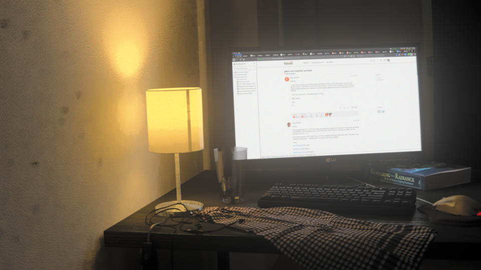
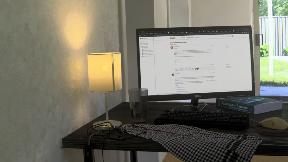
This is a luminance render of the work desk lit only by a cheap artificial desk lamp from IKEA. It is adjusted with human exposure adjustment, so there is a slight desaturation and ability to see the depths of the room.
To judge the human exposure adjustment, there is only my word as evidence of actually sitting in that space looking at the scene at night. Radiance does an excellent job at what is an incredibly complex field of human interpretation. One immediately visible flaw is the glare given off by the computer monitor. At night, after the screen is on for a while, this glare is not visible. Other than the glare, I can only give a qualitative statement where I claim that the real life scene and the render look quite similar.
Let's see how it compares to a photo.
For completeness, here is a colour version.
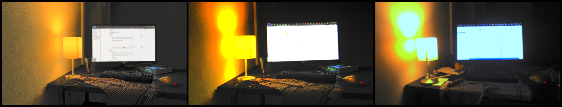
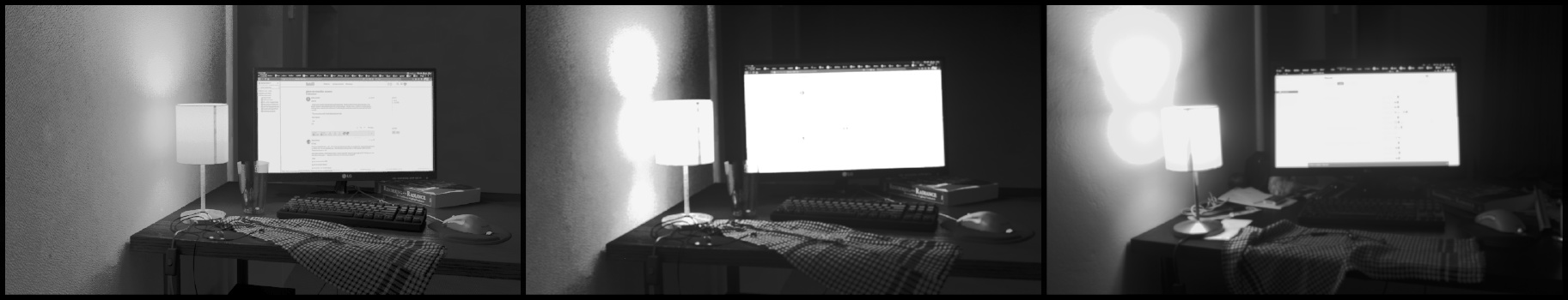
This comparison of three images represents a greyscale version of the original luminance render on the left. On the right is a photograph of the actual room taken with a phone camera set on automatic. Naturally, the photograph has the desk lamp shown as overexposed. The camera also captures lighting effects not visible to the human eye, such as a blue tinting to the computer monitor, and the extremely reflective surface of the desk. In real life, the desk is much less specular.
In the centre, it shows a photo taken of the render of the left. This naturally "adds" the layer of camera exposure imperfections (subject to the brightness clipping of the computer screen).
For qualitative results, which is the purpose of this render, it is suffice to say that they look rather similar. Here is another night time shot that shows more of the room.
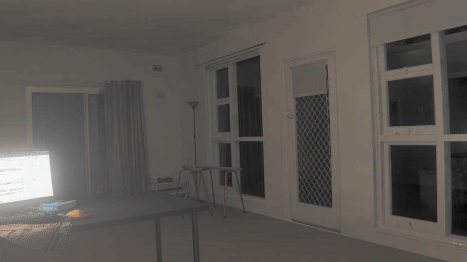
Let's see it in the daytime.
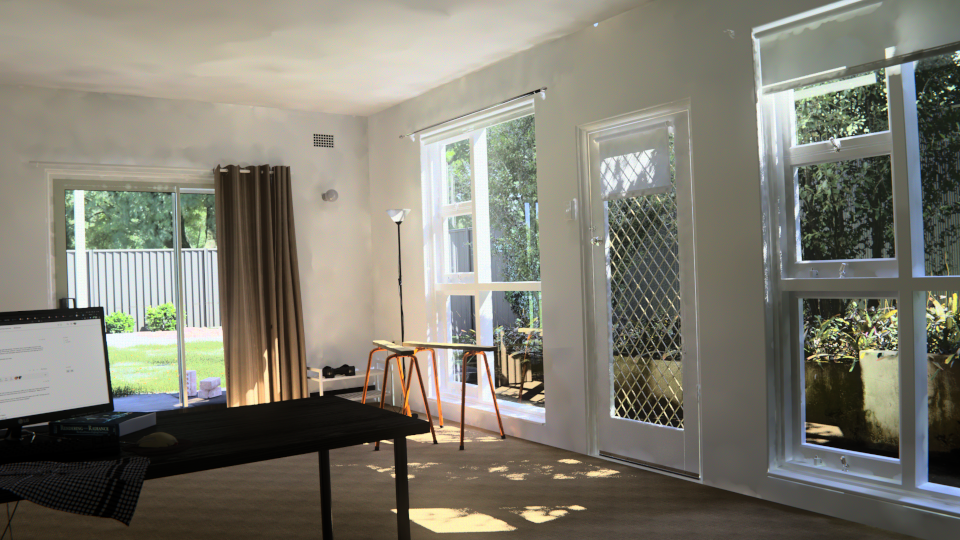
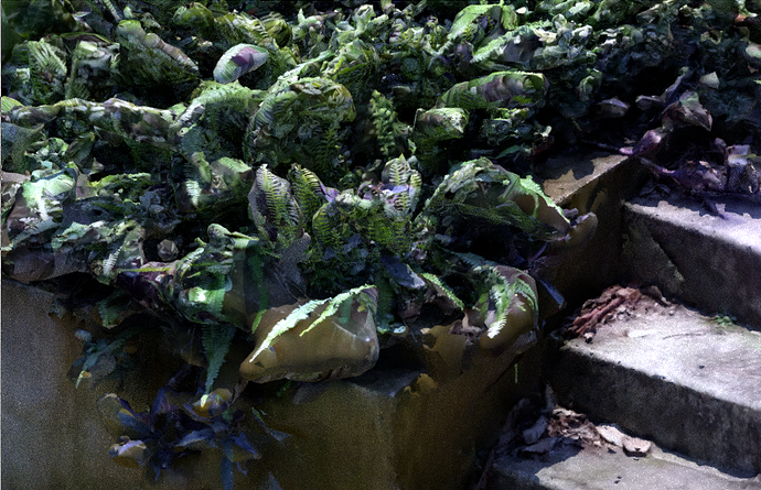
This daytime render shows the entirety of the living room taken from behind the desk with human exposure adjustment. There is a variety of entourage in the scene, as well as a glimpse of the backyard outside, turf grass, perimeter fencing, and planter bed to the right.
Again, there is only a claim made by myself that it does look indeed quite similar to the real life scene.
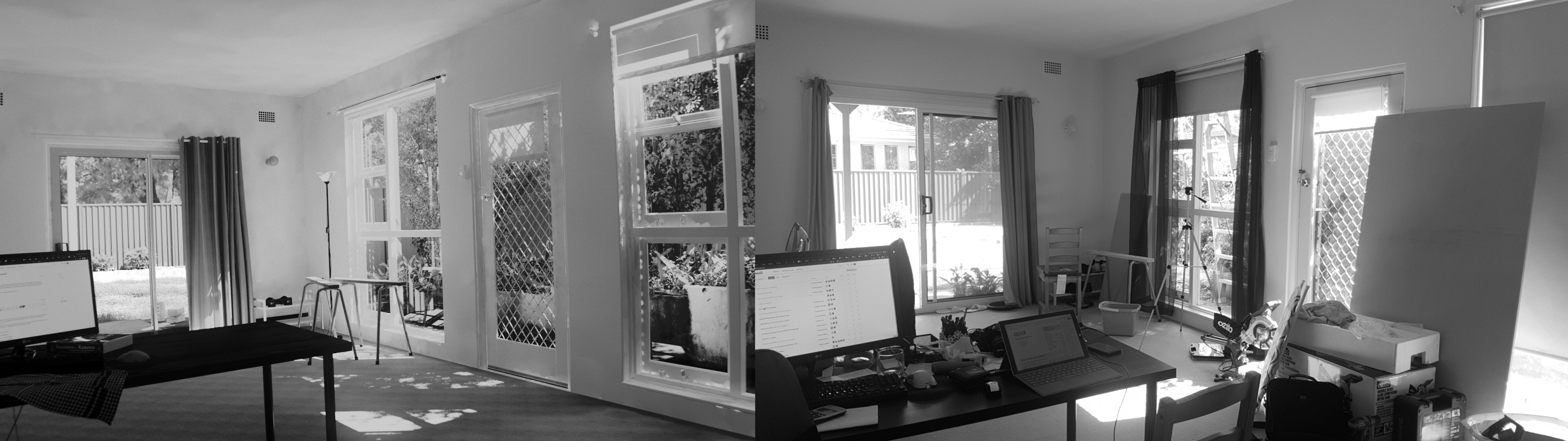
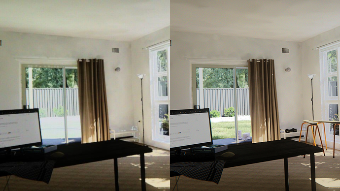
To help others appreciate the similarity, here is a greyscale comparison. The render is on the left and the phone camera photo (on automatic settings) is on the right. The photo is not quite exactly the same in terms of time of day, contents of the living room (a lot more messy in real life!), and camera position. However, it is enough to qualitatively admit that they are quite similar. No extra manipulation (apart from the greyscale filter) was done on either the render or the photo.
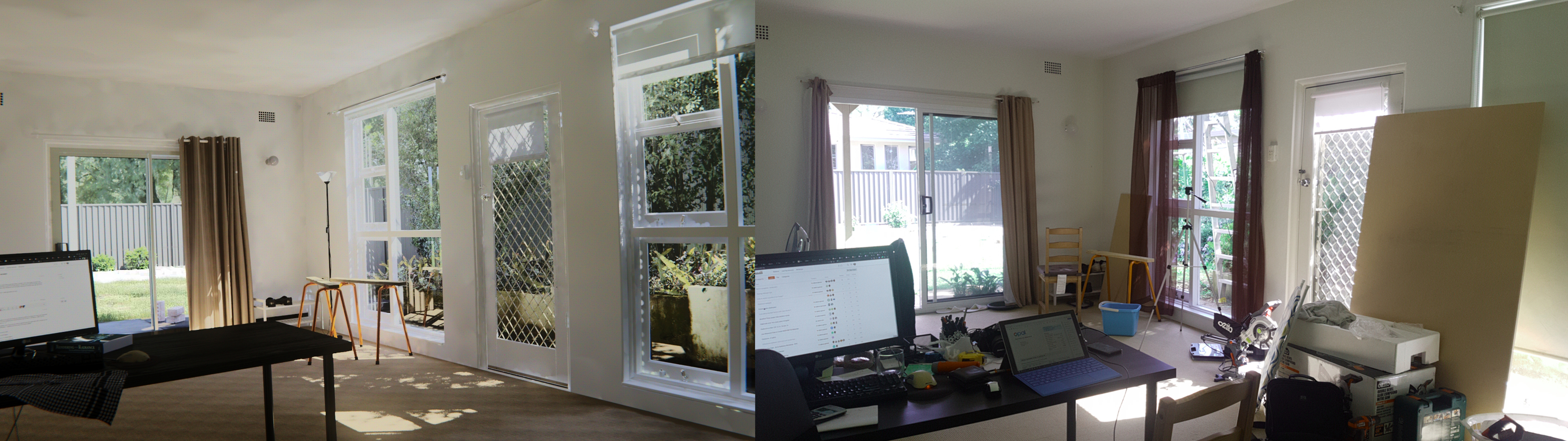
For completeness, here is a colour version.
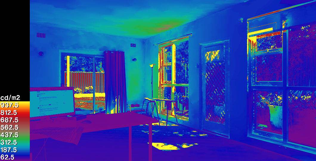
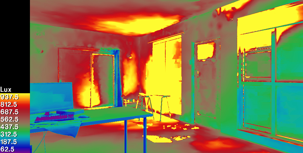
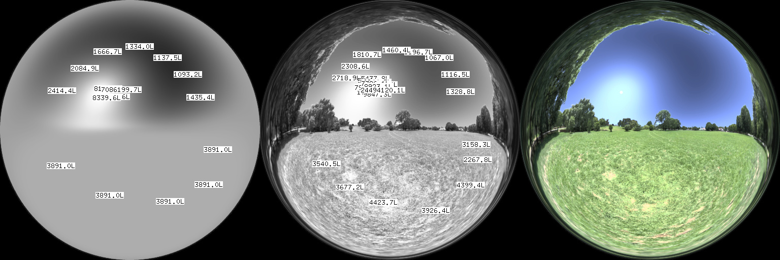
To bring some numerics to this primarily qualitative exercise, this falsecolour luminance render shows the range of values seen in the render.
Similarly, a falsecolour illuminance render is shown to give an idea of the range of values.
To complete the set of images, here is the work desk again, this time rendered in the day time.
As a bonus, a panoramic VR environment of the room is supplied that uses WebVR and can be viewed on any computer or phone. If you have a form of cardboard VR goggles, you can view the scene using them.
Capabilities demonstrated by the render
The objective of this render was to essentially use Radiance with techniques that are usually only used in a more traditional CG workflow. However, there was one prerequisite: the render had to be done "blind".
CG artists usually render by creating test renders, and then slowly tweak the scene until it matches the look they are aiming for. For this "blind" render, no artistic license was taken with these renders. There were no tests or tweaks, all of the data was entered and the render is final (unless further data can be added or re-measured to improve scientific accuracy). All geometry was taken from measurements of real life objects (with one exception to do with foliage, which is described later). All materials are also taken from real life measurements in a different environment. The render is a result of careful numeric input of measurements on top of the pillars of scientific validation in Radiance's history. This "blind" render methodology was to prove the ability to reliably predict the look of a unbuilt space simply by measuring samples of objects.
Apart from the "blind" render, here are some other capabilities demonstrated:
- Only vanilla Radiance is used, so the scene is written with a text editor (Vim) without using any frontend. Meshes use OBJ files that can be created from any software (in this case, Blender is used)
- Both low and high polygon meshes are used to build a scene
- Diffuse and specular maps in material definitions (normal maps are not used, due to Radiance's inability to displace objects along the normal Z axis)
- A mixture of texture maps and procedural textures are used
- Usage of particle driven vegetation generation
- Usage of duplivert (instance) based vegetation generation
- Usage of photogrametrically scanned objects
- Artificial lighting using
.iesdata of a lamp, placed in a luminaire - Geolocated CIE sky natural lighting, with a time of day
- A calibrated environment map, combined with the CIE sky
- A non-trivial scene asset organisation structure, with reusable assets, dividing the scene into different parts.
- Panoramic rendering, for use in static VR, with a VR demo included
- Cross platform support, all this work was done in Linux, but no Linux specific technologies are used
Asset structure in the scene
The assets were largely split into three areas for organisation:
- The living room and the objects inside
- The planter bed seen to the right and all of its groundcover plants
- The backyard with turf, fencing, and trees
Splitting the assets meant that should a portion of the scene change, the entire octree didn't need to be recompiled. The scene was then further split into:
- Individual items of furniture or entourage
- Individual instances of plants
- Individual patches of turf
The assets were organised into atomic directories following a proposed Radiance Filesystem Hierarchy Standard. This allowed the scene to include many objects without being overly complex in its programmatic definition.
A brief glance at
scene.rad and the
Makefile demonstrates the
succinct, intuitive, human description of all elements that are present in the
scene.
Mesh modeling and objects
The meshes were included in Radiance using mesh objects. This is described in
my beginners tutorial to
Radiance. This by itself is
enough to immediately create a lot of realism in the scene.
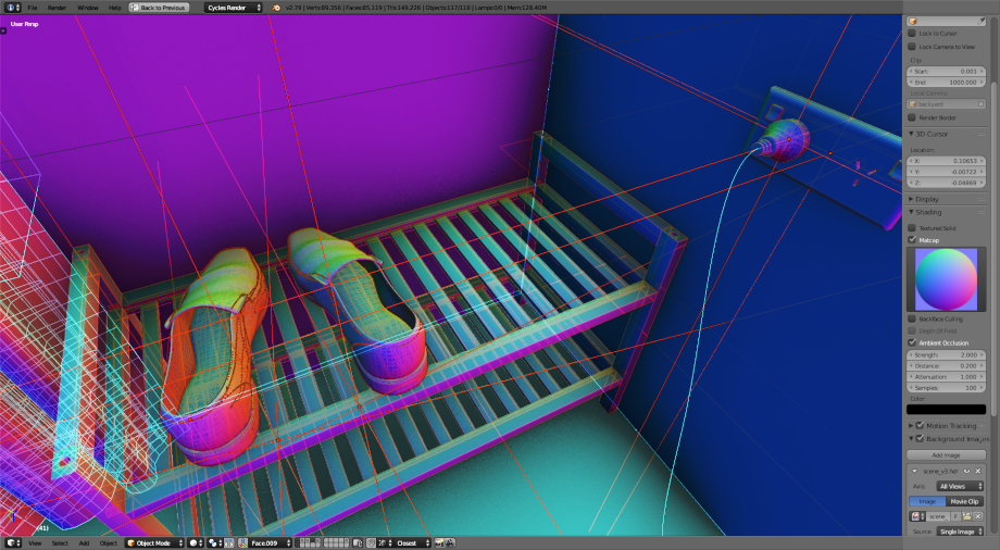
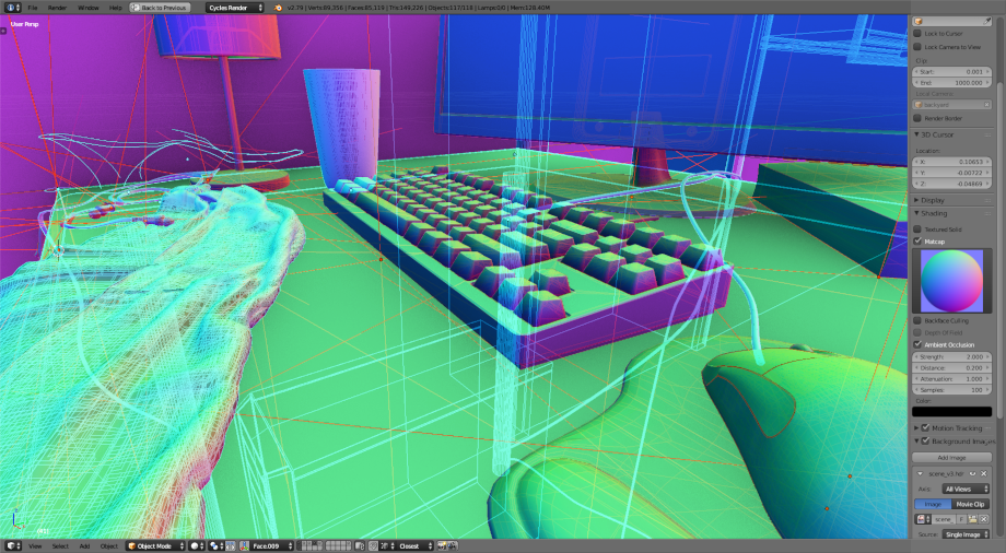
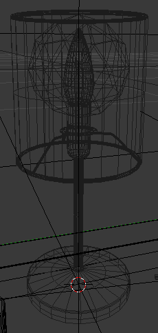
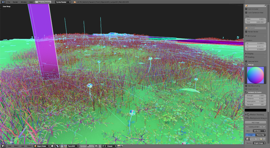
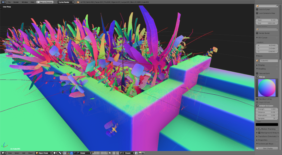
Here's a wireframe view of the scene. Relatively standard CG modeling practices are used here. Examples include maximising quad meshes to improve mesh topology, and using bevels to give realistic edges.
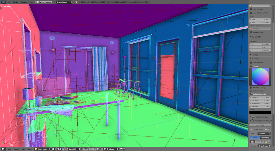
Let's take a look at the wireframes of some of the more detailed aspects of the scene. This gives an idea of the level of detail in modeling required.
Materials and textures
In order to record materials, every real life object was brought outside into
bright clear sunlight, and measured using the macbethcal method. I've detailed
how to calibrate textures using
macbethcal in another
post, but essentially this involves a RAW photograph of the material sample
together with
a colour checker chart. The average RGB of the diffuse material is then measured
after running macbethcal, and any CG diffuse texture map then is scaled to
that measured RGB. Specular and roughness values were guessed based on sensible
values, with help from examples of specular and roughness in
Radiance.
Some materials could not be brought outside, such as the carpet or wall. However
carpet or wall close to a window in ideal conditions can still be measured using
macbethcal. In the future, I plan to invest in some accurate artificial
lights.
Translucent materials had their transparency measured using a luxmeter placed in front of and behind the object. Multiple measurements were taken at different times of day and an average taken of the results.
Artificial lighting
Only one artificial luminaire is present in the scene: the desk lamp. This is a
cheap luminaire bought from IKEA, which originally came with a clear LED candle
bulb that is no longer sold. The LED lamp contained a reflector which casted
rather interesting shadows, but unfortunately no .ies file is provided.
However, this lamp can be replaced with any cheap generic bulb, and so there is
no guarantee that users of the space will choose that particular bulb.
As a result, I replaced the original lamp with a cheap, relatively
omnidirectional bulb that you might expect to find at the shops (in other words,
an easier bulb to simulate). Online, I found an .ies file by Cree, that
provided the same shape, temperature and lumen output of the simpler bulb.
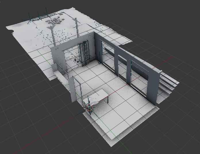
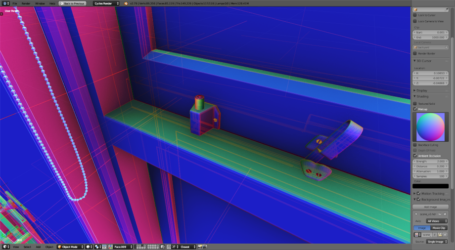
Therefore, it isn't the exact same bulb, but is similar. The nighttime render
verifies that the bulb behaves as expected. You can see the .ies sphere shape
relative to the luminaire in the picture below. The bulb itself, although not
seen in the render, contains glow materials.
The computer monitor is also technically an artifical light source. The good news is that all computer monitors are roughly the same in terms of brightness, and that Greg Ward has already measured a VDU (visual display unit) in the past, at 250cd/m2. Therefore his material settings were copied verbatim.
The environment lighting is created using both a CIE sky and a typical HDRI environment you might find in CG renders. The HDRI map was multiplied to give a ballpark correct figure for grass on a sunny day, and then a mask was applied to remove the sky portion of the HDRI map.
The sky portion was replaced with a gensky CIE sky with parameters for the
geolocation and a solar disc for the sun. As such the primary lighting is
provided by the sky, but the scaled HDRI environment helps add a bit of
variation within the ballpark values, but does not significantly adversely
affect the simulation.
Any surrounding context that was expected to actually affect the simulation was modeled, and therefore the HDRI image was limited to subtle background effects.
Vegetation particles
As in regular CG, a few variations of plant stems and leaves were modeled. These could then be instanced in various locations, rotations, and scales using the typical instancing tools. In Blender, the feature is known as "particles", but the method of growing and placing objects in a render, usually used for vegetation, is well established.
Radiance does not have any particle distribution tools, but it does support
instancing. Therefore in the case of the backyard grass, a script was written to
copy a patch of grass up to 50 times in an area. I describe more about how to
create vegetation in
Radiance in another post.
You can see the script generated
grass.rad which sets out
the instances for each species of grass.
Instances were deleted where they were not visible from the point of view of the camera.
Whereas the grass leaves were fully modeled (but not textured), the herbacious vegetation in the planter bed was only semi modeled (but fully textured). Each fern frond, leaf, or stem, was merely an alpha mapped plane. This was done to optimise the rendering time.
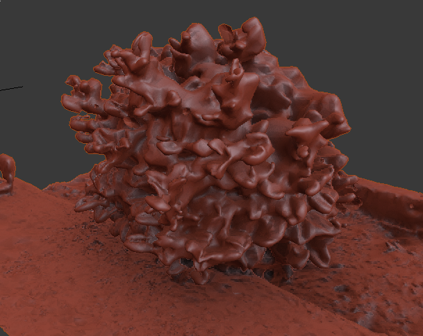
Vegetation photogrammetry
Photogrammetry with Poisson reconstruction is generally not the right tool to scan moving, thin, homogenous surfaces. This can be seen in the bulbous backfaces in the mesh reconstruction of these ferns in the planter bed.
Perhaps another reconstruction technique, such as my proposed point cloud mesh reconstruction using metaballs, may be more successful, but were not used in this render.
From a distance, mesh reconstructions may still be viable. Often, a UV map is generated from the projected raster photos that make up the scan. This is much harder to calibrate, as it is a messy collage of photos. For a bush, where you generally only care if the leaf is within the ballpark of correct values, and you are only seeing it from a distance, it is acceptable to use this technique.
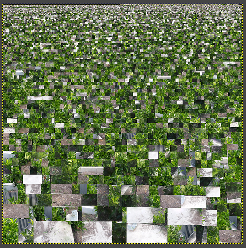
This type of scanned entourage offers much more realism than the alternative technique of alpha mapped planes for far away vegetation.
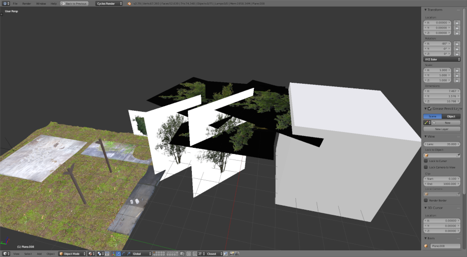
Alpha mapped trees
There are a few trees planted in the planter bed, and beyond the planter bed. In this render, an alpha mapped plane was used, where the tree texture was calibrated. The side effect of not using a fully modeled tree is that the shadows will not be truly correct, especially as the light generally hits at quite a sharp angle to the alpha mapped plane, which causes it to cast shadows that can't be seen from the room.
The position and shape of these dappled shadows are not critical to the scientific accuracy, as long as they exist. Therefore the tree was placed in the horizontal plane, to represent the canopy of the tree, and to cast the shadows. If viewed from another angle, this would look absolutely ridiculous, but for the purposes of simulating from this camera angle, it does what it needs to.
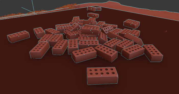
Rigid body simulation placed bricks
A nearly invisible part of the render is a pile of bricks in the backyard. I don't actually have a pile of bricks in my backyard, but they do show that any regular CG technique is still applicable, so long as it can be baked into a mesh. In this case, a rigid body simulation was used to drop them and have them pile naturally.
Panoramic 360 VR
A static, panoramic 360 VR was created from this render. This means that you cannot move around in the space, but you can look around 360 degrees, just like Google StreetView. This is a old trick that has been around for a long time, but Radiance has been around longer than that, and so it is not too intuitive how to achieve this.
I've written a tutorial on how to create 360 VRs with Radiance that covers all
the steps required. The scene.rif includes commented out sections that
describe how to create a 360 VR using the three techniques described in the
tutorial (angular map, cube map, and equirectangular map). The equirectangular
map is the preferred approach.
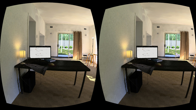
After rendering out the panoramic image, it needs to be displayed in a real time viewer. Nowadays, there are plenty of open source solutions that provide this function. I have used A-Frame, which is a WebVR script that runs in your browser. You can view a demo of the Radiance VR. If you have cardboard VR goggles, which you can buy as a cheap flatpack online, you can put your phone in and move your head around to see the scene.
Full inspection of the sources
The living room render is a fully open-source creation available for your
inspection. It is released under a CC-BY-SA 4.0 license, and you can browse the
Radiance living room source files
for free online here. It is also a public rsync directory, so you can download
it as follows:
rsync -avz rsync://sevenstrokes.net/bin/living-room .
Some of the more reusable assets have been reshared and are available in the free 3D Radiance model repository.