Radiance can be used to create three different types of 360 panoramic images for use in virtual reality (VR). A 360 panoramic is often used for a static VR image, where the viewer can rotate their head and look around, but not move around the space nor interact dynamically with objects.
The trick often works by placing the viewing camera inside of a sphere or cube, and mapping the 360 panoramic image as a texture to the inside of the sphere or cube. Looking around, this sphere or cube is set in a special way to not cast any shadows nor have any calculated lighting to give away the illusion that you are inside a sphere or cube, and then you can see the environment around you.
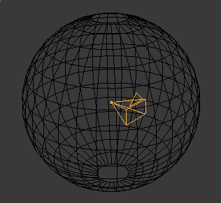
This technique has many names, known as a sky map, environment map, or sphere / cube map (specifically if the texture is created for a sphere or cube shape). It's quite an old and established technique, often used to create a background sky or environment in a 3D scene. The principle is exactly the same in VR, with the exception that you might create two images: one for the left eye and one for the right eye. The slight displacement creates a stereoscopic view that gives the illusion of depth.
Choosing the type of 360 texture you create depends on what your viewing system allows. There are three types:
- Angular sphere map
- Equirectangular panoramic
- Cube map
Creating an angular sphere map
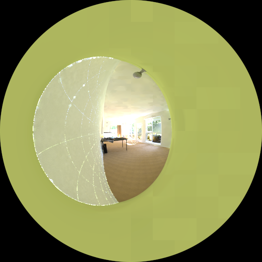
The most straightforward option is to create an angular sphere map / fisheye render. This type of render is circular, with the center of view in the center of the render, and 360 around the perimeter of the render.
The advantage is that it's really easy. The disadvantage is that distortion increases as the view moves behind you (i.e. towards the perimeter of the rendered circle). This can create a pinch-like artifact in the VR.
This is very simple to render by setting the following options to rpict, and
by setting a square (e.g. 1024 x 1024 px) output resolution:
-vta -vv 360 -vh 360
If you already have an equirectangular projection render (see below), you can
alternatively convert it to a sphere map with imagemagick.
Creating a cubemap
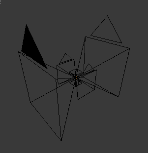
The second most straightforward option is to create a cube map. This involves 6 different views, each corresponding to an inside face of a 6-sided cube. The views are front, back, left, right, up, and down. Often, VR software requires that you format it in a certain order, or name them specific file names, or rotate them by 180 or 90 degrees.
This is beneficial as it is basically 6 renders instead of one, and therefore can minimise any distortion in the VR. However, it does mean that you are rendering six views instead of one, and can take a lot longer. However, as it is a simple perspective view, you can benefit from doing a partial render / patch render instead of rendering absolutely everything if you make a small change.
Each view is a perfect square, and is usually a power of 2, such as 1024x1024.
Each view covers a vertical and horizontal field of view of 90 degrees, so that
they combine to create a 360 image. This means that the following options can be
used in your .rif file provided to rad.
view=front -vtv -vh 90 -vv 90 -vp 0 0 0 -vd 0 1 0 -vu 0 0 1
view=back -vtv -vh 90 -vv 90 -vp 0 0 0 -vd 0 -1 0 -vu 0 0 1
view=left -vtv -vh 90 -vv 90 -vp 0 0 0 -vd -1.0 0 0 -vu 0 0 1
view=right -vtv -vh 90 -vv 90 -vp 0 0 0 -vd 1 0 0 -vu 0 0 1
view=up -vtv -vh 90 -vv 90 -vp 0 0 0 -vd 0 0 1 -vu 0 0 1
view=down -vtv -vh 90 -vv 90 -vp 0 0 0 -vd 0 0 -1 -vu 0 0 1
# Must be square!
RESOLUTION=1024 1024
Notice that the -vp coordinates remain constant in all views. This is
assuming that you want to define "front" as being perfectly facing 0 1 0 (the
+Y axis). What is front and what is back doesn't usually matter in VR, as you
can turn around anyway, but the front view is usually what is presented first,
and so it might be sensible to set it to a visually interesting direction.
It may be that you have a different position or view direction and view up
vector. You will have to calculate these yourself. However, if you use Blender,
you can use this script in my beginner Radiance
tutorial to calculate the
-vu and -vd options.
Once the views are rendered, you may need to rotate with protate or pflip if
your VR software requires you to. These are pretty straightforward to apply.
To ensure visual consistency, the views need to be adjusted to the same exposure
values, otherwise you will see the seams of the cube. To solve this, we first
calculate the combined histogram of all of your views. Assuming all your 6
.hdr files are in the same directory, you can run:
$ phisto *.hdr > combined.hist
$ pcond -I < combined.hist front_original.hdr > front_adjusted.hdr
$ pcond -I < combined.hist back_original.hdr > back_adjusted.hdr
$ pcond -I < combined.hist left_original.hdr > left_adjusted.hdr
$ pcond -I < combined.hist right_original.hdr > right_adjusted.hdr
$ pcond -I < combined.hist up_original.hdr > up_adjusted.hdr
$ pcond -I < combined.hist down_original.hdr > down_adjusted.hdr
You can still run a human adjustment by doing:
$ pcond -I -h < combined.hist front_original.hdr > front_adjusted.hdr
[ ... etc ... ]
Alternatively, if you know the exposure value you want it to be (for example, let's say it's "-2"), you can run:
$ pfilt -1 -e -2 front_original.hdr > front_adjusted.hdr
[ ... etc ... ]
Once adjusted, you may be expected to combine the images together. There are
many formats. One example format, is where each images are shown one after
another in a 6x1 strip of tiles. You can do this with pcompos and the -a
argument:
$ pcompos -a 6 front.hdr back.hdr left.hdr right.hdr up.hdr down.hdr > cubemap.hdr
You should change the order depending on what order your VR software expects. As another example, this'll give you a 3x2 strip of tiles:
$ pcompos -a -3 front.hdr back.hdr left.hdr right.hdr up.hdr down.hdr > cubemap.hdr
All done!
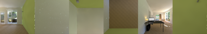
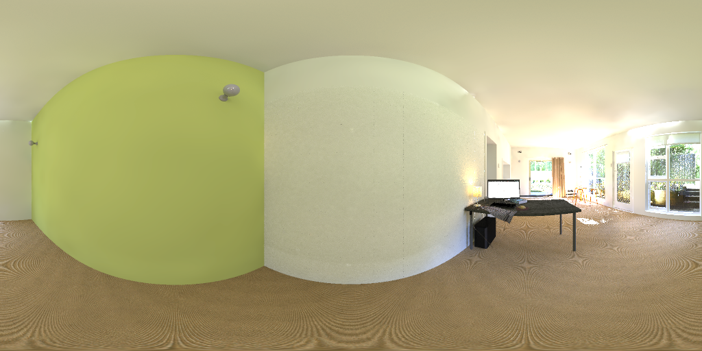
Creating an equirectangular projection
An equirectangular projection is something like the world map. The 360 view can be represented in a single 2x1 width x height aspect ratio image, with the expense of having distortion towards the poles.
One approach to creating an equirectangular projection is to first render a
sphere map, and then use a tool like imagemagick to convert the distortion.
You can read up more about circular distortions to see the full set of options. In short, the following will convert from sphere to equirectangular, known as a DePolar distortion:
$ convert sphere.jpg -distort DePolar 0 equirectangular.jpg
Unfortunately, unlike the sphere map where we could tell rpict to use -vta
and the cube map where we could use -vtv, there is no view type for an
equirectangular projection. However, Mark J. Stock
(who does some fantastic computational artwork which you should check out!) has
created a cal
file
that allows us to do just that. I have modified it slightly to produce a single
360 image, instead of a stereoscopic pair, which I'll talk about later. So
first, please download this 2d360.cal file.
Because we will use this .cal file to influence how to calculate each pixel,
we will need to render our image in a slightly different way. But first, let's
save our output settings into saved.opt from rad:
$ rad -v 0 scene.rif OPT=saved.opt
Now you can render it using the following command. You will need to replace X=0;Y=0;Z=0 with your -vp's X, Y, and Z coordinates. You will also need to replace NCORES with the number of CPU cores that you have, to take advantage of multiprocessor rendering. Finally, replace scene.oct with your octree.
$ X=2048; Y=1024; cnt $Y $X | rcalc -f 2d360.cal -e "XD=$X;YD=$Y;X=0;Y=0;Z=0" | rtrace -n NCORES -x $X -y $Y -fac @saved.opt scene.oct > out.hdr
This creates a 2048x1024px output image. That's it!
Creating a stereoscopic panorama
A stereoscopic panorama is the same as a monoscopic panorama, except that you create two of them: one for the left eye, and one for the right. Therefore, the most important factor is the inter-pupillary distance (IPD). This is the distance between your eyes and is usually 0.055m and 0.07m for most people.
For the sphere map and cube map, it suffices to create another camera and render
out more views. For the equirectangular projection, Mark J. Stock's original
.cal file does the work for you by creating an over-under stereoscopic view.
This is a 1:1 output image with the left image on the top and the right image on
the bottom. You can download 3d360.cal here. Running 3d360.cal
needs a bit more work. Take note that the output resolution is square, and it
specifies a few more variables, such as IPD, EX, and EZ which you can read
what they mean in the .cal file. Here's the command:
$ X=2048; Y=2048; cnt $Y $X | rcalc -f cal/3d360.cal -e "XD=$X;YD=$Y;X=0;Y=0;Z=0;IPD=0.06;EX=0;EZ=0" | rtrace -n NCORES -x $X -y $Y -fac @saved.opt scene.oct > out.hdr
You may need to split over-under output into individual images, which you can do
easily with imagemagick:
$ mogrify -format jpg pano.hdr
$ convert pano.jpg -crop 1x2@ +repage +adjoin pano_%d.jpg
$ mv pano_0.jpg left.jpg
$ mv pano_1.jpg right.jpg
In a future post, I will walk through how to place this on the web using WebVR, which you can view using things like Cardboard VR.